This week I continued working on the distance sensor. Last week I successfully implemented a distance sensor that we can get results from the serial monitor. This week I decided to install a physical monitor and see if it could show the distance detected in real time.
OLED SSD1306 Test
Arduino / C++ — OLED SSD1306 Counter Test (Debug by ChatGPT)
#include <Wire.h>
#include <Adafruit_GFX.h>
#include <Adafruit_SSD1306.h>

#define SCREEN_WIDTH 128
#define SCREEN_HEIGHT 64
#define OLED_RESET -1
#define OLED_ADDR 0x3C

Adafruit_SSD1306 display(SCREEN_WIDTH, SCREEN_HEIGHT, &Wire, OLED_RESET);

void setup() {
  Serial.begin(115200);

  // Use board default I2C pins
  Wire.begin();
  Wire.setClock(100000);

  if (!display.begin(SSD1306_SWITCHCAPVCC, OLED_ADDR)) {
    Serial.println("SSD1306 init failed");
    while (true) delay(10);
  }

  display.clearDisplay();
  display.display();

  Serial.println("OLED initialized");
}

void loop() {
  static uint32_t counter = 0;

  display.clearDisplay();

  // Visual proof it works
  display.drawRect(0, 0, 128, 64, SSD1306_WHITE);
  display.fillRect(5, 5, 30, 20, SSD1306_WHITE);

  display.setTextColor(SSD1306_WHITE);
  display.setTextSize(2);
  display.setCursor(45, 10);
  display.println("TEST");

  display.setTextSize(1);
  display.setCursor(45, 40);
  display.print("Count: ");
  display.println(counter++);

  display.display();
  delay(200);
}
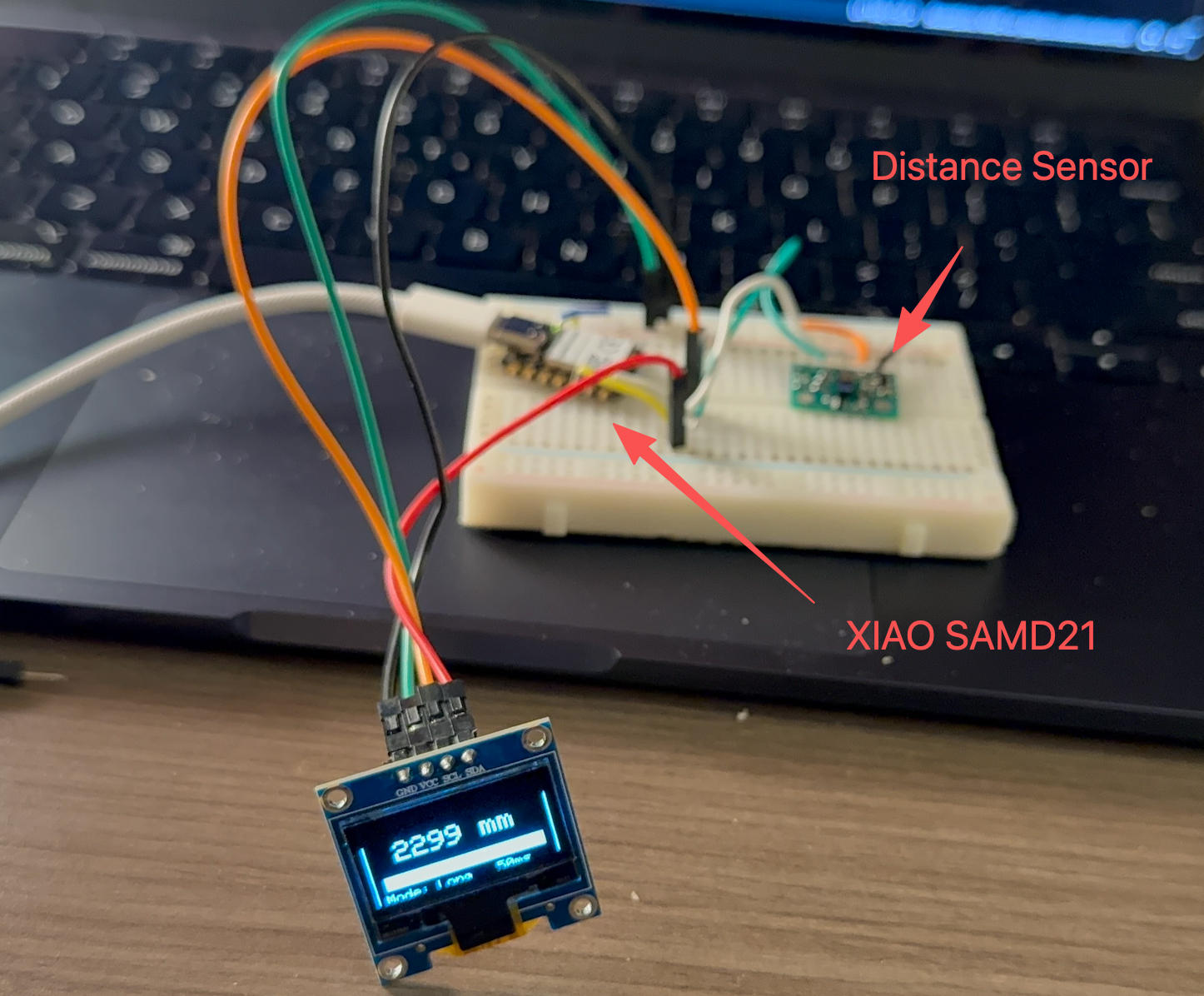
VL53L1X Distance Sensor with OLED Display
Arduino / C++ — VL53L1X + OLED Distance Bar UI (Debug by ChatGPT)
#include <Wire.h>
#include <VL53L1X.h>
#include <Adafruit_GFX.h>
#include <Adafruit_SSD1306.h>

#define SCREEN_WIDTH 128
#define SCREEN_HEIGHT 64
#define OLED_RESET -1

Adafruit_SSD1306 display(SCREEN_WIDTH, SCREEN_HEIGHT, &Wire, OLED_RESET);
VL53L1X sensor;

// Adjustable display scale
const uint16_t MAX_DISPLAY_MM = 2000; // bar max = 2 meters

void drawFrame() {
  display.drawRect(0, 0, 128, 64, SSD1306_WHITE);
  display.drawLine(0, 10, 127, 10, SSD1306_WHITE);
}

void setup() {
  Serial.begin(115200);
  delay(300);

  Wire.begin();
  Wire.setClock(100000);

  // OLED init
  if (!display.begin(SSD1306_SWITCHCAPVCC, 0x3C)) {
    while (1);
  }

  display.clearDisplay();
  display.setTextColor(SSD1306_WHITE);

  // Sensor init
  if (!sensor.init()) {
    display.setCursor(10, 30);
    display.setTextSize(1);
    display.println("VL53L1X FAIL");
    display.display();
    while (1);
  }

  sensor.setDistanceMode(VL53L1X::Long);
  sensor.setMeasurementTimingBudget(50000);
  sensor.startContinuous(50);

  display.clearDisplay();
  display.display();
}

void loop() {
  uint16_t mm = sensor.read();
  bool timeout = sensor.timeoutOccurred();

  display.clearDisplay();
  drawFrame();

  // ---- Header ----
  display.setCursor(4, 2);
  display.setTextSize(1);
  display.print("TOF DISTANCE");

  // ---- Distance value ----
  display.setTextSize(2);
  display.setCursor(20, 18);

  if (timeout) {
    display.print("----");
  } else {
    display.print(mm);
    display.print(" mm");
  }

  // ---- Distance bar ----
  uint8_t barX = 8;
  uint8_t barY = 42;
  uint8_t barW = 112;
  uint8_t barH = 10;

  display.drawRect(barX, barY, barW, barH, SSD1306_WHITE);

  if (!timeout) {
    uint8_t fillW = map(
      constrain(mm, 0, MAX_DISPLAY_MM),
      0, MAX_DISPLAY_MM,
      0, barW - 2
    );
    display.fillRect(barX + 1, barY + 1, fillW, barH - 2, SSD1306_WHITE);
  }

  // ---- Footer ----
  display.setTextSize(1);
  display.setCursor(6, 55);
  display.print("Mode: Long   50ms");

  display.display();
  delay(80);
}
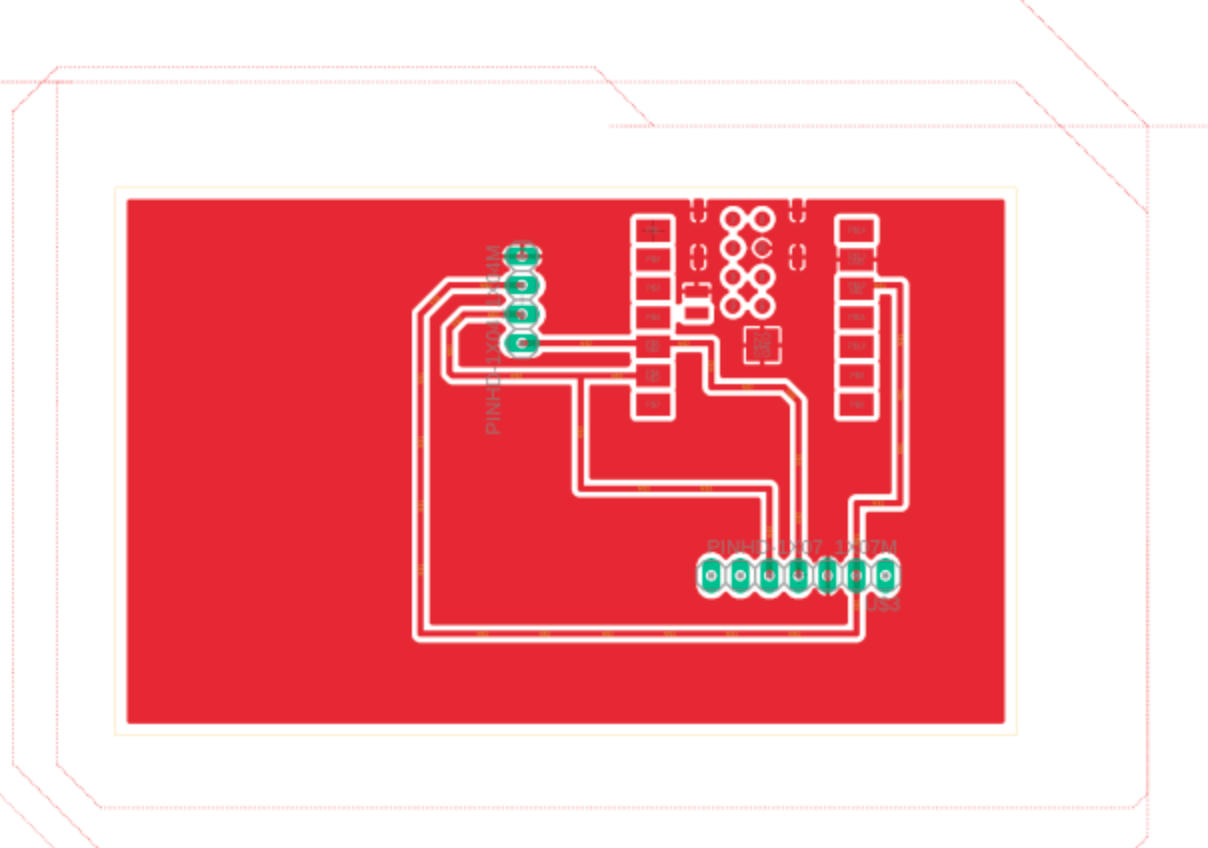
PCB Design